The antenna design is meant for NASA’s Jupiter-bound Juno spacecraft, and is being used to build two of the six antennas that make up Juno’s Microwave Radiometer, or MWR, instrument. The result of the team’s effort is likely the first all-metal microwave patch array antenna. Juno is slated to launch in August 2011, and the innovative new antenna design is a direct answer to the challenge posed by the high-radiation environment in which the spacecraft will operate.
Patch antenna arrays employ a grid of individual antenna elements, or patches, to detect or transmit electromagnetic energy. In the case of MWR, the antenna receives electromagnetic radiation at microwave frequencies. The arrays are highly sensitive to the direction that radiation comes from. Many such instruments have been flown on space missions, but all have employed dielectric, or non-conductive, materials in the construction of the antenna elements. Patch antenna elements are typically constructed using printed circuit techniques, where the shapes of the patch and associated feed circuits are literally printed on to a circuit board. Each antenna patch is a metallic film or sheet set on a dielectric substrate. The substrate supports the patch a certain distance above the antenna structure to which all the patches in the array are affixed. The patch is fed a signal, commonly from a coaxial cable, and all the patches in the array form a signal that can be used to measure the direction and intensity of radiation.
The Juno mission calls for a specialized approach, due to the intense particle radiation the spacecraft will encounter near Jupiter. The planet’s powerful magnetic field accelerates electrons and ions to enormous energies, and these electrons will penetrate dielectrics, where they will build up and eventually discharge. Thus the Jupiter environment demands that all spacecraft surfaces be metalized or otherwise engineered to dissipate electric charge in order to avoid sparks and problems with static electricity. The solution devised by Neil Chamberlain and colleagues eliminates the dielectric patch substrate and supports each patch on a wide metallic post. According to the team, this was not the obvious approach.
The group originally had planned to use a conventional dielectric-supported patch element in their design. To cope with the extreme radiation environment, they used carbon-doped dielectric materials that included Astroquartz honeycomb and a film adhesive. The carbon-laced glue was intended to dissipate electric charge before it could build up, but there was a problem: the team discovered that adding carbon to the adhesive reduced its bonding strength, rather like adding dirt or some other contaminant. Richard Hughes, a member of the antenna team, explains that it seemed the engineers would either have to add so much carbon to their glue that they would not get good adhesion, or they would not have enough carbon to dissipate a charge. “This only became apparent by doing a lot of testing,” Hughes says. “In normal, routine DC resistance measurements, everything looked good. But when we charged up the materials with an electron beam in a vacuum chamber, we found that things weren’t operating as we expected them to.”
This news came in late 2008, and with the Juno mission well into the implementation phase, the team was required to deliver two finished patch array antennas by the third quarter of 2009. Unless their antenna element could withstand the harsh environments of launch and Jupiter orbit, the MWR instrument could be in jeopardy.
Such situations are not uncommon during spaceflight hardware construction, and faced with this potential showstopper, the experienced team’s ingenuity revealed an unexpected path forward. The first half of the solution came from Chamberlain, working on another front. He had been studying the potential problems micrometeoroid impacts would cause for the antennas. “The thinking was that a particle would rip through the metal and leave a vapor trail that would cause a short circuit, thus interrupting the antenna signal,” he says. So Chamberlain conducted a series of simulations in which he modeled short circuits at various locations around the antenna to characterize the effects. To his surprise, it turned out that there were large areas near the center of the patch where short circuits would not significantly affect the antenna’s performance. “I thought, what if we had a whole lot of short circuits in the center of the patch, like you’d get with a metallic central supporting post?” he says.

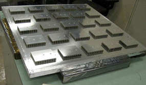
The second part of the solution came from team member Julie Jakoboski, who determined that the housings for the power divider circuits on the back side of the antenna could be machined from aluminum to very high tolerances – with walls only 20 thousandths of an inch (about 500 microns) thick. Usually the circuits for antennas of this type are printed onto a dielectric substrate using photolithography techniques.
Chamberlain continues, “So then I wondered if we could use the precision machining techniques Julie came up with for the power divider housings to machine the antenna patch with a supporting metallic post. This would allow us to eliminate the dielectrics in the antenna element altogether.”
If Chamberlain’s hunch was right, the antenna team could create a low-weight all-metal antenna patch that would be relatively simple to manufacture and fasten to the antenna panel. Additionally, the new antenna element design would utilize all of the existing feed hardware on the back of the panel, causing minimal disruption to the already proceeding hardware build.
With this potential remedy in hand, the team put their revised design through a rigorous development and testing program in lightning fast time, proving the new approach to their instrument in just 40 days. Such work often takes many months, and the engineers managed this coup while continuing their work on the rest of the MWR antennas and components.
The new all-metal patch array brings with it several ancillary benefits. Since the frequency at which a standard patch array antenna operates is dependent on the dielectric properties of the patch substrate, eliminating the dielectric disposed of the main source of uncertainty in the antenna’s frequency tuning. The team also can detach the new antenna elements if the need arises, whereas before, they were fixed firmly with adhesive. This is thanks to a bolt-on approach devised by Hughes that fastens the central post firmly to the array without the need for adhesives. Finally, the revised design also has superior thermal properties, allowing for longer sun-exposure during launch.
And since, as Jakoboski notes, it is no small a challenge to make an instrument that is lightweight despite being large and made of metal, the team was pleased that their revised design would increase the mass of the two antennas by less than a kilogram.
Eliminating the dielectric material from the Juno antenna has potential applications for other missions as well. With increasing frequency, dielectrics cause problems with signal loss. For this reason, the all-metal patch element approach has caught the eye of a JPL radar instrument team, who are considering concepts for designing a landing radar that operates at 95 GHz. A dielectric-free design would make for a less lossy system in that wavelength range.
For Juno, the MWR antennas represent an entirely new technique for peering deep into Jupiter’s atmosphere. The microwave experiment will measure the abundance of water in Jupiter – which is key for understanding how the planet formed – and reveal how the deep atmospheric circulation is connected to the planet’s visible meteorology.
Links
- NASA's Juno Website - http://www.nasa.gov/juno